

Instructions
We've been working on this diagnostic tool for quite some time with the goal of making remote vehicle diagnostics simpler and more accessible for everyone. Our main idea was to help technicians and enthusiasts use their existing aftermarket diagnostic tools to connect to vehicles remotely — just as if they were sitting in the workshop next to the car.
The system is entirely software-based, but it also supports optional hardware devices that enable more advanced communication with the vehicle using CAN bus technology . With the complete setup, you can work over CAN bus , Ethernet , and even perform EEPROM read/write operations on certain modules through Bench mode.
Our goal is to provide a reliable and flexible solution for workshops and independent technicians who want to diagnose, code, and program vehicles remotely without complex configurations.
Selecting a Server
When the Main App starts, it automatically retrieves a list of all available servers that can be used for the connection.
Each server displays its current ping, which indicates the communication latency between your device and the server. For the best performance, select the server with the lowest ping value.
A lower ping generally provides a faster and more responsive connection, resulting in a better user experience.
You can change the selected server at any time in the settings.
When you select a server from the available server list, the Main App, the Client Device, and the Server Device all establish secure connections to the selected server.
Once connected, the server creates a private virtual network (VPN) between all participating devices. Within this virtual network, the devices can communicate with each other as if they were connected to the same local network, regardless of their physical location.
The Client App and Client Device maintain a persistent connection to our server infrastructure. This allows them to receive status updates, remain reachable, and automatically connect to the appropriate VPN server when a technician initiates a session.
Connecting to Server Device
Before connecting, ensure that the Server Device and the computer running the Main App are connected to the same local network.
The application will automatically search for available Server Devices on the local network. Once the desired Server Device appears in the list, select it to establish the connection, click "Connect"
Click "Skip" if you want to bypass this step and connect directly to a Client App instead.
Connecting a Client
When the application starts and you reach the CAN Bus Device section, click the “Skip” button.
After skipping, you'll see a field labeled Client ID . When customer launches the application, their ID should appear in the list. Select the desired ID from the list to connect to that client.
Important: Do not run both applications on the same computer. Each instance must run on a separate device in order for the connection to work properly.
Communication Modes
By default, the application starts in BMW ENET mode. This mode requires no additional setup.
The application also supports VAG DoIP and BMW ICOM communication modes. You can switch between these modes in the Settings menu by using the corresponding toggle switches.
Make sure to select the correct communication mode that matches your connected vehicle before starting the connection.

Virtual Network Adapter
The application runs a virtual network adapter in the background. By default, this adapter uses the IP address 10.10.1.1, which represents the vehicle's local IP address. This is the address that all diagnostic tools will recognize as the car's network interface.
The IP address of this adapter can be changed manually if needed. Some diagnostic tools only work with addresses in the 169.254.x.x range, so you can adjust the adapter's IP to match those requirements. Be careful not to set an address that conflicts with another network adapter on your system — if a conflict is detected, the application will notify you automatically.
Broadcast Mode
At the top of the application window, you'll find a Broadcast button. When enabled, this mode makes the communication available across your entire local network.
For example, if the main application is running on one computer, and another device is connected to the same local network, that second device can also connect to the vehicle through the network. In this case, the connection should be made to the IP address of the main computer on the local network.
If broadcast mode is turned off, diagnostic tools must be run on the same computer where the main application is running, since the connection will not be visible to other devices on the network.
WARNING: Only enable broadcast mode if you actually intend to access the car from another machine. If you run the tools on the same computer while broadcast mode is enabled, some tools may not function properly.
Client-Side Application
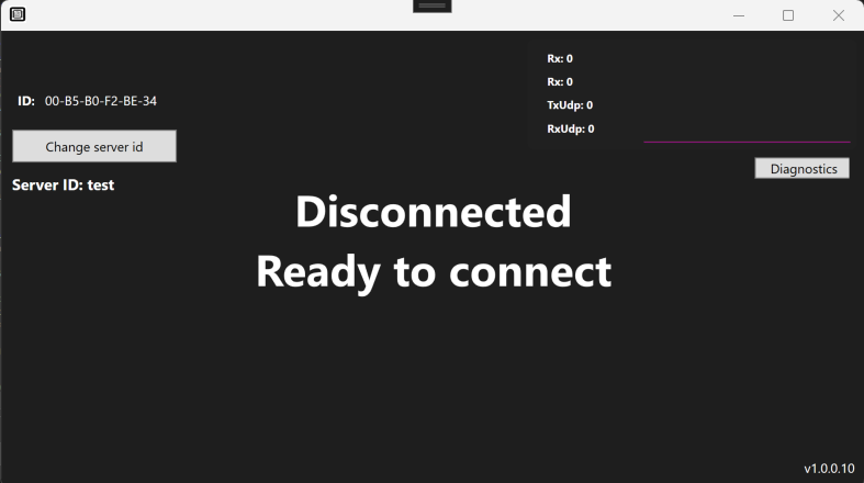
The same firewall rules mentioned earlier also apply to the client-side application. Make sure no third-party firewall or antivirus software is blocking the connection, otherwise the client will not be able to communicate with the main app.
In the client application, under the Change ID field, you need to enter the Main Application ID . This ID can be found in the top-right corner of the main application window. Once entered, the client app will be ready to connect and operate.
The vehicle must be connected via Ethernet using the appropriate adapter ( ENET , ICOM ). Connect the car either directly to the laptop running the client application, or to the same local network where that laptop is connected. As long as both devices are on the same network, the communication will work correctly.

Red arrow: ICOM found and connected — indicates that the car has been successfully detected and is currently connected.
Yellow arrow: KL-line status indicators (KL30, KL15, Status) — show the current voltages of the connected vehicle. Status also shows whether ICOM is reserved or released. ( Available only in ICOM mode )
Blue arrow: Live UDP/TCP communication graph — visualizes network traffic between the client and tool in real time. While you are trying to use aftermarket tools and a connection is established, it indicates that communication is active.
Green arrow: Current IP address of the car and the “Change IP” button — displays the assigned local car IP address. This is the IP you can use to connect aftermarket tools to the application. If you enable broadcast mode, this changes to 0.0.0.0 , which means you can connect through any local IP address available on the laptop.
On the left side of the screen, you can see the Voltage indicator. This value is reserved for the connected CAN bus device and has no functional meaning if you are only using the applications without the hardware. Next to it, you'll find the Ping display, which shows the current communication latency between the two apps — the higher the number, the slower the communication. If the text Connection lost appears instead of the ping value, it means that the connection has been interrupted, for example due to an internet outage or other network issues.
ICOM
- Reserve / Release – this button let you lock or free up the ICOM. This is especially important when using aftermarket diagnostic tools , as many of them only work when the ICOM is in reserved mode .
- Reboot ICOM – this button restarts the ICOM device. It's useful if the device becomes unresponsive or if there are network issues and you want to reset it without physically unplugging it.
If there are multiple ICOMs connected to the local network - for example, in a workshop environment - the application automatically detects all of them.
When this happens, a popup window appears in the main app where you can select which ICOM you want to use.
Each listed ICOM shows:
-
the device name ,
-
its IP address ,
-
the VIN number of the last connected vehicle, and
-
the MAC address ,
so you can easily identify the correct one.
Once you've selected and connected to an ICOM, the application will communicate only with that device until it's disconnected.
Pairing a Client Device
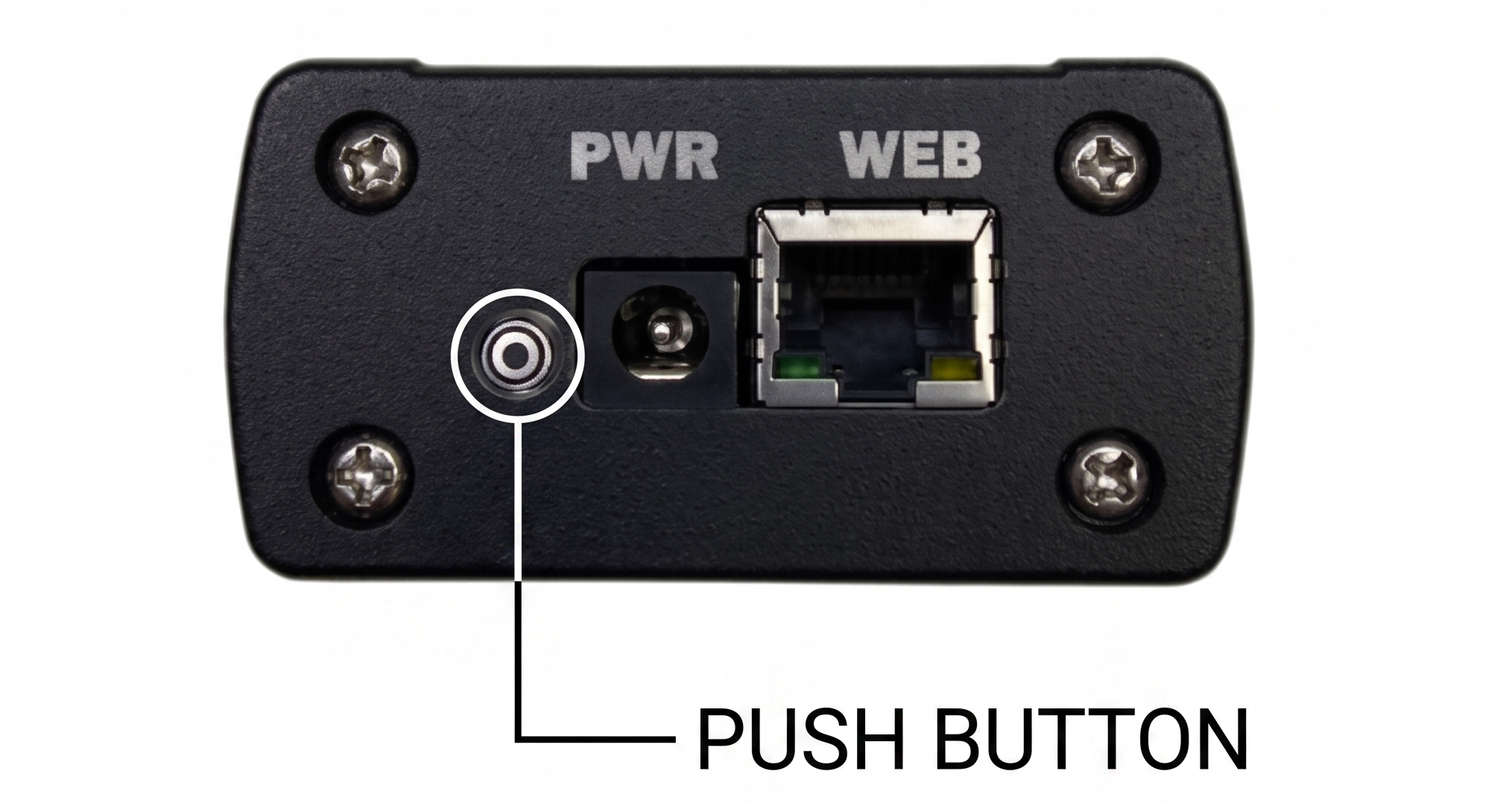
Before pairing a Client Device, make sure that both the PC running the Main App and the Client Device are connected to the same network.
- Open the Main App and sign in with your account.
- Ensure that the Client Device is powered on and connected to the same local network as the PC.
- Press and hold the button on the Client Device for approximately 5 seconds until a confirmation notification appears in the Main App, indicating that the device has been successfully paired
- Once the pairing process is complete, the Client Device will be linked to your technician account.
After successful pairing, the Client Device can be accessed remotely through the Main App, allowing the technician to monitor and manage it from anywhere with an internet connection.
Ethernet Communication
To access the Head Unit or establish an SSH connection, you must first enable Ethernet Forwarding Mode.
- Enable Ethernet FWD Mode.
- Turn on the Head Unit switch located on the right side of the application window
- Wait a few moments while the communication channel is established.
Once the connection is ready, the Head Unit status bar will display the device information and connection details, indicating that the communication has been successfully established.
After the connection is active, you can access the Head Unit and use SSH or other supported Ethernet-based communication features like HTTP.
Sharing Clients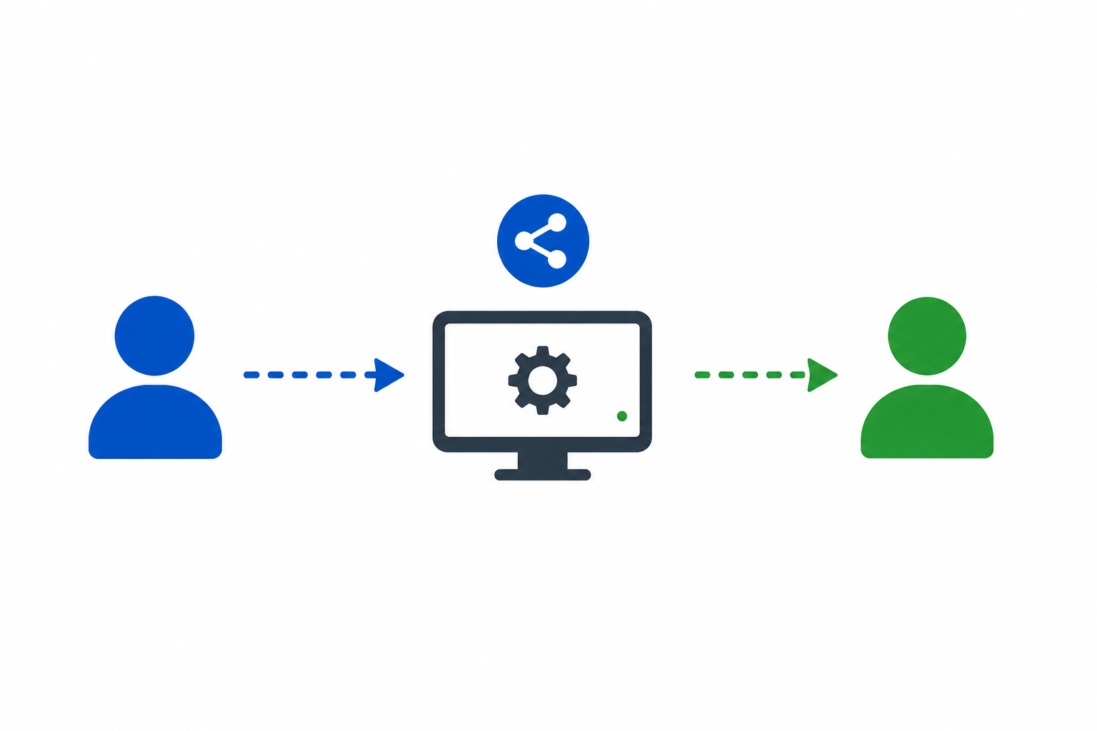
The Share Clients feature allows you to grant another technician access to one of your client.
To share a client, first connect to one of your own Client. Then click the Share Clients button located in the top toolbar.
Two sharing modes are available:
Temporary Sharing
Temporary sharing grants another technician access to the selected Client Device/App until the Client Device/App is restarted.
After either of these is restarted, the temporary access is automatically revoked, and the client remains assigned to the original technician.
Permanent Sharing
Permanent sharing transfers ownership of the Client to another technician.
Once the transfer is complete, the original technician will no longer be able to connect to that Client Device. From that point forward, only the newly assigned technician will have access to it.
Note: Permanent sharing is intended for ownership transfers and cannot be automatically reversed. Make sure you select the correct technician before confirming the transfer.
System Diagnostics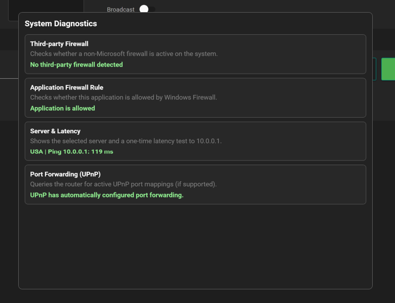
The System Diagnostics window provides a quick overview of the current system status and helps verify that all required network components are configured correctly before establishing a connection.
The diagnostics panel includes the following checks:
Third-party Firewall
Verifies whether a third-party firewall is installed and active on the system. Third-party firewall software may interfere with incoming or outgoing network connections.
Application Firewall Rule
Checks whether the application has been granted permission to communicate through Windows Firewall. If the application is blocked, remote connections may not function correctly.
Server & Latency
Displays the currently selected server and performs a latency test. For the best performance, choose the server with the lowest available ping.
Port Forwarding (UPnP)
Checks whether the router supports UPnP (Universal Plug and Play) and whether the required port forwarding rule has been configured automatically. When successful, no manual router configuration is required.
DCAN Communication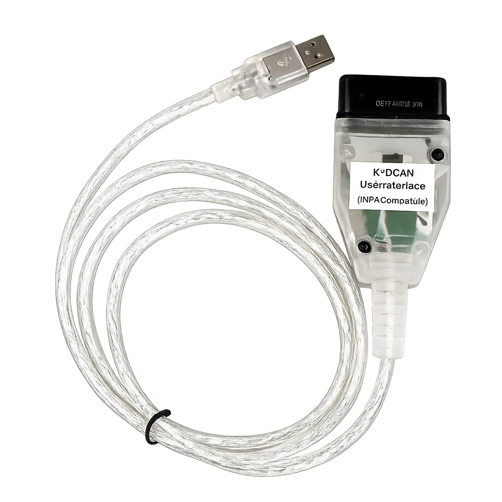
The DCAN feature allows the Main App to communicate remotely with a DCAN interface connected to the Client Device.
Before using DCAN, open the Settings menu in the Main App and enable the DCAN feature.
To establish a DCAN connection:
- Enable DCAN in the Settings menu.
- Connect the DCAN interface to the computer running the Client App.
- In the Main App, switch to DCAN Mode.
Once DCAN Mode is activated, the Main App automatically establishes communication with the remote DCAN interface. After the connection is ready, the DCAN interface can be used in the same way as if it were connected directly to the technician's computer.
Serial Protocol
Serial protocol allows to connect remotly to MEVD family modules with TC1797 processors . Protocol allows to read/write EEPROM and flash from processor. Tools like PCMFlash , ACDP , FLEX can be connected to server device and then client device connects to DME.
CAN Communication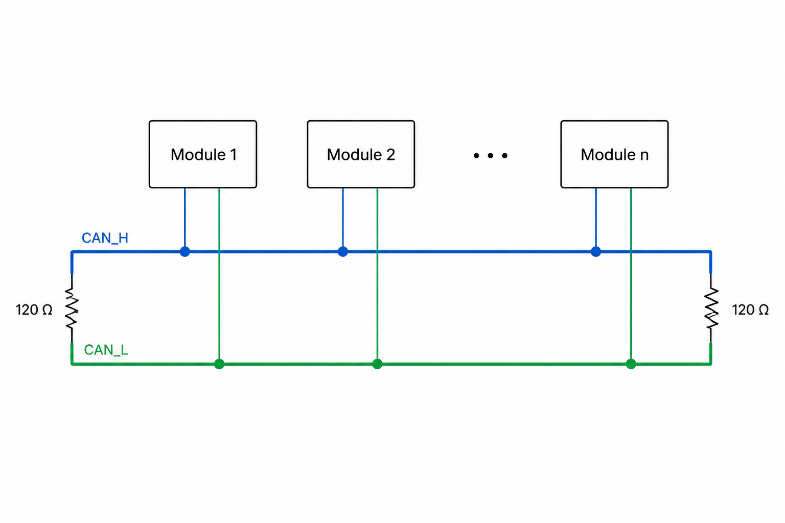
The CAN Communication mode enables transparent CAN message forwarding between a Client Device and a Server Device.
To use this feature:
- Connect the Client Device to the vehicle's CAN interface.
- Connect the Server Device to the CAN interface of the diagnostic tool.
- In the Main App, switch to CAN Mode.
Once both devices are connected and CAN Mode is enabled, all CAN messages are forwarded between the Client Device and the Server Device. This allows the diagnostic tool to communicate with the vehicle as if it were connected directly.
CAN Configuration
CAN Bitrate
You can set the CAN bus bitrate to match the network used by the vehicle and the diagnostic tool. The default bitrate is 500,000 bit/s which is suitable for most automotive CAN networks.
Ensure that the selected bitrate matches the CAN bus configuration. An incorrect bitrate will prevent communication.
CAN Filters
The Main App also supports CAN ID filtering.
One or more CAN IDs can be specified as filters. When filters are configured, only CAN frames matching the specified CAN IDs are forwarded between the Client Device and the Server Device. All other CAN traffic is ignored.
CAN Monitoring and Scripting
In addition to forwarding CAN traffic between the Client Device and the Server Device, the Server Device also forwards every CAN frame to the Main App. This allows CAN messages to be monitored, analyzed, and processed in real time.
The Main App provides two independent scripting systems, each designed for a different purpose.
Both the Status Monitoring Script and the CAN Command Script are stored as plain text (.txt) files.
Scripts can be created or edited using any text editor, such as Notepad, and then saved with the .txt extension.
To load a script into the Main App:
- Prepare or edit the script in a text editor.
- Save the file as a .txt file.
- In the Main App, click the Select Script button.
- Browse to the desired script file and open it.
The selected script is loaded immediately and becomes available for execution.
Status Monitoring Script
The Status Monitoring Script is intended for continuously monitoring vehicle states by evaluating incoming CAN messages.
The processed values can be displayed directly in the application, making it easy to monitor important vehicle information during a remote session.
CAN Command Script
The CAN Command Script, available at the bottom of the CAN Bus window, is designed for sending CAN messages and creating automated CAN communication sequences.
A command script can be used to:
- Send predefined CAN frames.
- Execute command sequences with configurable delays.
- Wait for specific CAN responses.
- Filter and display selected CAN IDs in the log window.
- Process received data before displaying it.
- Create simple diagnostic or testing procedures.
This makes it possible to automate repetitive CAN operations without manually sending each frame.
Script Commands
WAIT
Pauses the script for the specified amount of time.
WAIT(1000)
Waits 1000 ms (1 second) before executing the next command.
REPEAT
Restarts script execution from the specified line.
REPEAT(1)
Restarts the script from line 1, allowing continuous execution.
SEND
Sends a CAN frame.
SEND(12#1234)
Sends a CAN message with:
- CAN ID: 0x12
- Data: 12 34
Example:
SEND(7DF#0201000000000000)
RECEIVE
Receives CAN frames with a specified CAN ID.
Log messages without blocking
RECEIVE(12)(LOG)
Every received frame with CAN ID 0x12 is displayed in the log window. Script execution continues immediately.
Wait until a frame is received
RECEIVE(12)(LOG)(W)
The script pauses until a CAN frame with ID 0x12 is received, then writes it to the log.
Store raw data
RECEIVE(12)(DATA1)
Waits for a CAN frame and stores its raw payload in the Data1 field.
The following destination fields are available:
DATA1DATA2DATA3DATA4
Example:
RECEIVE(7E8)(DATA2)
Transform received data
RECEIVE(12)(DATA1)(T)
Waits for a CAN frame, processes the received data using transformation commands, and displays the final result in the Data1 field.
The transformation section must always end with:
END_RECEIVE
or
END_RECEIVE(text)
where the optional text is appended to the displayed value.
Example:
END_RECEIVE( km/h)
may display:
72 km/h
Data Transformation Commands
Transformation commands operate on the received CAN payload.
SELECT
Extracts one or more bytes.
SELECT([start],[end])
Extracts bytes from [start] to [end].
Examples:
SELECT(1,1)
SELECT(3,4)
SELECT(2,10)
DEC
Converts the selected bytes from hexadecimal into a decimal number.
Example:
10 → 16
IF
Replaces a numeric value with text.
IF([condition],"ON")
If the current value equals [condition], it becomes:
ON
Example:
IF(0,"OFF")
IF(1,"ON")
Bitwise Operations
Supported operations:
XOR FF
AND 0F
OR 80
NOR FF
NAND FF
NOT
These commands perform standard bitwise operations on the current value.
Arithmetic Operations
Basic arithmetic can also be applied.
+10
-5
*2
/4
These operations are executed in the order they appear.
Examples
RECEIVE(12)(DATA1)(T)
SELECT(1,1)
DEC
*2
END_RECEIVE
Step-by-step explanation
- RECEIVE(12)(DATA1)(T)
- Waits for a CAN frame with ID 0x12.
- The received data will be processed and displayed in the DATA1 field.
- SELECT(1,1)
- Extracts the first byte from the CAN payload.
- DEC
- Converts the hexadecimal value to decimal.
- *2
- Multiplies the decimal value by two.
- END_RECEIVE
- Finishes the transformation and updates the DATA1 field.
Example
Received CAN payload:
10 25 45
Processing:
SELECT(1,1)   → 10
DEC           → 16
*2            → 32
END_RECEIVE   → 32
The DATA1 field will display:
32
RECEIVE(456)(DATA2)(T)
SELECT(2,3)
AND 0FFF
DEC
/10
END_RECEIVE( km/h)
Step-by-step explanation
- RECEIVE(456)(DATA2)(T)
- Waits for a CAN frame with ID 0x456.
- The processed result will be displayed in the DATA2 field.
- SELECT(2,3)
- Extracts bytes 2 and 3 from the received payload.
- AND 0FFF
- Clears the upper four status bits, leaving only the 12-bit value.
- DEC
- Converts the hexadecimal value to decimal.
- /10
- Applies the scaling factor.
- END_RECEIVE( km/h)
- Displays the calculated value followed by the text km/h.
Example
Received CAN frame:
456#80 03 E8 12 45 00 00 00
Processing:
SELECT(2,3)   → 03 E8
AND 0FFF      → 03 E8
DEC           → 1000
/10           → 100
END_RECEIVE   → 100 km/h
The DATA2 field will display:
100 km/h
Network Setup (Peer-to-Peer Connections)
The following network configuration is only required if you plan to use the application in Peer-to-Peer (P2P) mode.
If you connect through one of the available servers, no router configuration is necessary. In this case, you can safely skip this section, as all communication is routed through the selected server.
For Peer-to-Peer connections, your router must allow incoming connections on the required ports. There are two ways to configure this, depending on whether your router supports UPnP (Universal Plug and Play).
Option 1 – Enable UPnP (Recommended)
The easiest way to get started is by enabling UPnP on your router. This allows the application to automatically open the required ports without manual configuration.
How to enable UPnP:
- Open your router's web interface . You can usually do this by entering your router's IP address in your browser - for example,
192.168.0.1or192.168.1.1. - Log in with your administrator username and password.
- Go to a section such as Advanced , Network , or NAT Forwarding (the exact name depends on your router model).
- Find the UPnP setting and switch it ON .
- Save the changes and restart your router.
After that, start the application. If everything is working correctly, i nside the app click “ Settings“ and you'll see a message saying “UPnP OK” — this means the connection was set up automatically and no further steps are needed.
Option 2 – Manual Port Forwarding
If your router doesn't support UPnP, you can still make the application work by setting up manual port forwarding .
Steps to set up port forwarding:
- Open your router's web interface (for example, go to
192.168.0.1in your browser). - Log in with your admin credentials.
- Look for a section named Port Forwarding , NAT , or Virtual Server .
- Add two new rules with the following settings:
| Rule | Protocol | External Port | Internal Port | Device IP |
|---|---|---|---|---|
| 1 | TCP + UDP | 13000 | 13000 | (Your device running the app) |
| 2 | TCP + UDP | 15,000 | 15000 | (Your device running the app) |
After saving the changes, restart your router. Once done, start the application — it will now use the manually forwarded ports if UPnP is not available.